
AI-driven CAD automation for SolidWorks — an MCP (Model Context Protocol) server.
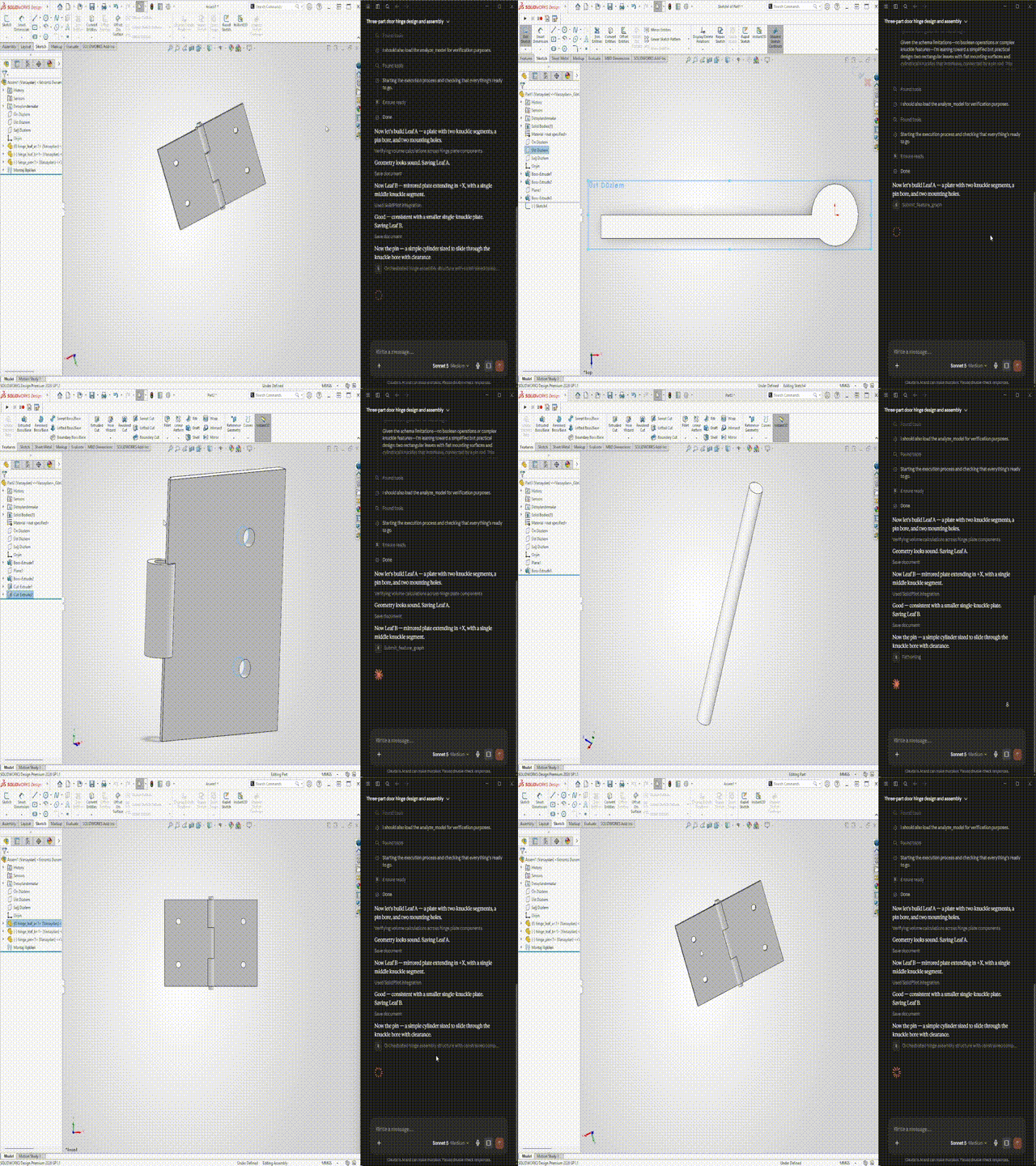
SolidPilot lets an AI model work with SolidWorks at the CAD feature level. The goal is for the model to reason in terms of "which CAD intent am I realizing?" instead of "which API method should I call?". Intent is converted into a CAD-neutral intermediate representation, and a deterministic compiler lowers that representation into concrete SolidWorks operations.
SolidPilot is not a Claude-only plugin; it is a general bridge between SolidWorks and AI. Because MCP is an open standard, any MCP-capable AI client can connect — alongside Claude, OpenClaw, OpenAI-based agents, and local LLMs are also targeted. The architecture was designed for this extensibility from the start: the execution and planner layers do not know which client is calling them; a thin adapter per client reuses a shared bridge core. adapters/claude/ is the current implementation; supporting a new AI client means only adding a new adapter.
Repository:
mcp-server-solidworks· Public name: SolidPilot · Target version: SolidWorks 2026
The SolidWorks API exposes thousands of methods. Presenting each one to the AI as a separate "tool" explodes context size and token cost — the economic problem that stalls similar projects.
SolidPilot solves this by raising the level of abstraction:
- The AI produces intent at the feature level (for example, "put a hole in the top face").
- That intent is expressed as a CAD-neutral Feature Graph IR.
- A deterministic compiler lowers the IR into ordered, concrete SolidWorks operations.
- A single feature therefore maps to many low-level operations, and one model call per request is enough.
Because the IR is the spine, the same machinery runs backwards: a 2D technical drawing is design intent expressed in two dimensions, so it can be read into the same IR and built.
Hand SolidPilot a .DXF or .DWG — the file a supplier or a customer actually sends, with no model behind it — and it reconstructs the part:
drawing.dwg → analyze_drawing → (draw dialect: views, edge classes, chained contours,
              true-valued dimensions, bend notes) → Feature Graph IR → compiler → SolidWorks
The reader decides which of two answers the drawing warrants. When every decision the part needs is forced by the drawing itself — today, sheet-metal flat patterns — it lowers the whole part to IR on its own and analyze_drawing(mode='build') builds it in one call. When the drawing needs real engineering reading (the normal case for a machined part), it says so and hands over the structured analysis, which the model interprets under a versioned rule set (the recipe://usage/reverse resource) and builds through submit_feature_graph.
Either way the result is checked, not assumed: expected volume is computed from the drawing's own dimensions before building and read back after. Nine real drawings have been reconstructed this way so far — four in-house samples (two of them sheet metal) and five production manufacturing sheets (A4/A3/A1, 1:1 to 1:10, three different title-block templates), each verified against its own title-block weight to within 0.02% or against the original part to exact topology.